The SIC9803 is a dimmable high precision primary-side regulation isolated flyback controller with single-stage Active PFC, specially designed for offline constant current LED lighting. The controller with on-chip PFC circuit operates in CCM (Critical Conduction Mode) to achieve high power factor and reduce the power MOSFET switching loss.
The controller precisely control the LED current without secondary side sense and feedback circuit including opto-coupler. It uses source driver architecture and pending internal charging circuit for low primary side switching loss, ultra fast VDD start up and LED turn on.
The SIC9803 uses compensation method to achieve excellent line regulation, and it still can be tuned externally for flexibility.The controller also has outstanding load regulation for driving wide range of LED numbers.
The SIC9803 offers rich protection functions to improve the system reliability, including LED short circuit
protection, LED open circuit protection, VDD over voltage protection, VDD under voltage protection, ISEN resistor short circuit protection, ISEN resistor open circuit protection, cycle-by-cycle current limit and die over-temperature protection.All the protection features are auto-recovery.
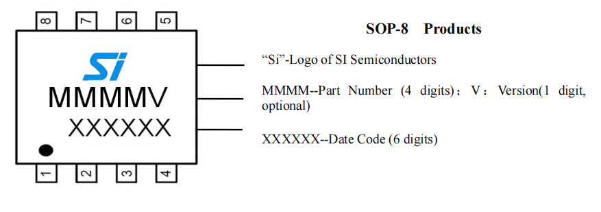
The SIC9803 is available in SOP-8 package.
Features
· Single-Stage Active PFC for High Power Factor and Low THD
. Primary Side Control Constant Current Operation
. Dimmable
. ±3% LED CurrentAccuracy
. Excellent Line and Load Regulation
. Critical Conduction Mode Operation
. Gate Driver Structure for Improved Efficiency
. High Resistance Feedback Resistor for Improved Efficiency
. Ultra-Low Start up Current
. Ultra-Low Operating Current
. LED Short and Open Circuit Protection
. ISEN Resistor Short and Open Circuit Protection
. Transformer Saturation Protection
. Cycle-by-Cycle Current Limit
. VDD Over-voltage and Under-voltage Protection
. Over Temperature Protection
. Auto Recovery
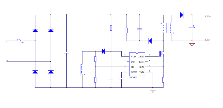
Typical Application
Pin Assignment
Functional Description
The SIC9803 is a high precision primary-side regulation isolated flyback controller with single-stage Active PFC, specially designed for offline constant current LED lighting,can achieve high power faction ,low THD and high efficiency.
Start-up
After system powered up, the VDD pin capacitor is charged up by the start up resistor. When the VDD pinvoltage reaches the turn on threshold, the internal circuits start working. The COMP pin voltage is pulled up to 1.5V quickly, then the SIC9803 starts the MOSFET driver. The system works at 10kHz frequency at the beginning, the COMP voltage rises up gradually, and the transformer primary peak current also rises up. The LED current hence achieves a soft start without overshoot. After the output voltage is built up, the VDD power is supplied by the auxiliary winding.
Constant Current Control
The SIC9803 uses compensation method to achieve excellent line regulation, and it still can be tuned externally for flexibility. Output current is given by:

Where,
Np is turns of transformer primary winding;
Ns is turns of transformer secondary winding;
VREF is the internal reference voltage, typical is 200mV;
RISEN is current detection resistor.
Feedback Network
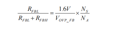
The SIC9803 detect the output zero current through feedback network,the FB sense down threshold is set at 0.1V, Hysteresis voltage is 0.08V.The FB sense is also used to detect output OVP,threshold is 1.6V. The ratio of FB upper resistor to lower resistor can be set :
Where,
RFBL:the lower resistor of the feedback network;
RFBH:the upper resistor of the feedback network;
VOVP:output over voltage setting point;
NS is turns of transformer secondary winding
The FB upper resistor can be set to around 300KΩ to improve the system efficiency. It is also used for finetuning the LED current line compensation.
Dimming function
SIC9803 with an adjustable light interface, through a simple peripheral circuit, can be compatible with DC dimming, PWM dimming and TRIAC dimming. DIM voltage linear dimming range is 3V - 1V, in this range, the output current is higher if the DIM voltage is higher. When the voltage on DIM is less than 0.7V, the signal for Gate will be closed, and the voltage on PIN COMP will pull down to 1.5V, the output current is will be zero. When DIM is greater than 3V, the chip is in normal working condition, and the output current is 100%.
Please connect a 100pF filter capacitor from PIN DIM to the ground if the Dimming is no need.
LED Over Temperature Protection
When SIC9803’s temperature are too high the output current will be decrease. The output power and thermal dissipation are also reduced. The system temperature is regulated and the system reliability is improved. The thermal regulation temperature is set to 150℃ internally.
LED Open Protection
The output voltage can be detected by the FB pin. When the FB voltage is higher than 1.6V, the LED open protection is triggered and the power MOSFET gate driver stops switching. After several seconds, the gate driver starts switching again.
LED Short Protection
The SIC9803 judges LED short from the FB voltage. During a shorted LED condition, SIC9803 reduces the internal command current to a very low level and slows down the switching frequency to 10 kHz to decrease the output current. Meanwhile, the output voltage is low and the VDD pin cannot be charged up by the output voltage, so the VDD pin voltage will gradually decrease and finally reaches the UVLO threshold. After the system enters into fault condition, the VDD voltage will decrease until it reaches UVLO threshold. Then the system will re-start again. If the fault condition is removed, the system will resume normal operation.
PCB Layout Guidelines:
Bypass Capacitor: The bypass capacitor on VDD pin should be as close as possible to the VDD and GND pins. Ground Path: The power ground path for current sense resistor should be short and wide, and it should be as close as possible to the IC ground (pin 8) , otherwise the LED output current accuracy maybe affected. The IC signal ground for COMP and FB components should be connected to the IC GND pin with short traces and should be away from the power ground path.
The Area of Power Loop: The area of main current loop should be as small as possible to reduce EMI radiation.
FB Pin: The feedback resistor divider should be as close as possible to the FB pin, and the trace must keeps away from dynamic node of the inductor, otherwise the FB pin OVP function might have risk to be mis-triggered by the system noise.